Ramp Meters
This document describes the inSIGHT ATMS Ramp Meter functionality. Full configuration of ramp meter controllers can be completed from the ATMS interface. Two services run related to ramp meters: RMP for communication with 2070 controllers, and MCCAIN to supply data from the RMP service to ATMS classic services (e.g. TRAF for travel time calculation)
General Concepts
The configuration model for the ramp metering service relies on three copies of configuration:
- ATMS: The copy of configuration held at the system configuration, which can be edited, saved, and sent to controllers
- Field: The copy of configuration that reflects the configuration in the controller, but is stored locally within the ATMS
- Controller: The copy of configuration that exists locally in the controller and is used to operate the ramp meter
Synchronization of the field and controller configuration copies is handled by the service. The service will regularly refresh the field configuration, and is also configured to refresh its copy of the field configuration when a change has been made to the controller local configuration
Within the ATMS UI, only the ATMS and field configuration are accessible. Loading configuration from field replaces the ATMS configuration with the field, but does not trigger the service to directly update the field configuration from the controller.
The Update Controller functionality in the UI updates the field configuration and sends changes to the controller. However, only changes between the ATMS and field configurations are sent to the controller. Specifically, controller configuration is separated into 38 distinct database pages. When a page includes a value that differs between ATMS and field configuration, that page is sent to the controller.
A 'Force Update' function to replace all configuration in a controller based on ATMS configuration will be available in version 6.8.
Ramp Meter Configuration
The Ramp Meter Configuration View allows authorized users to manage the configuration of each ramp meter, including general, communication, mainline and ramp lanes, miscellaneous, schedules and bins.
Common Items
Each screen in the ramp meter configuration window includes the following buttons:
- View Changes: a settings comparison window to view changes between ATMS and field configuration
- Load Settings from Controller: replace ATMS settings with field settings
- Save: save changes to ATMS configuration settings
- Update Controller: replace field settings with ATMS settings and send changes to field controller
- Reboot Controller: send a reboot command to the controller
- Cancel: close the window and discard unsaved changes.
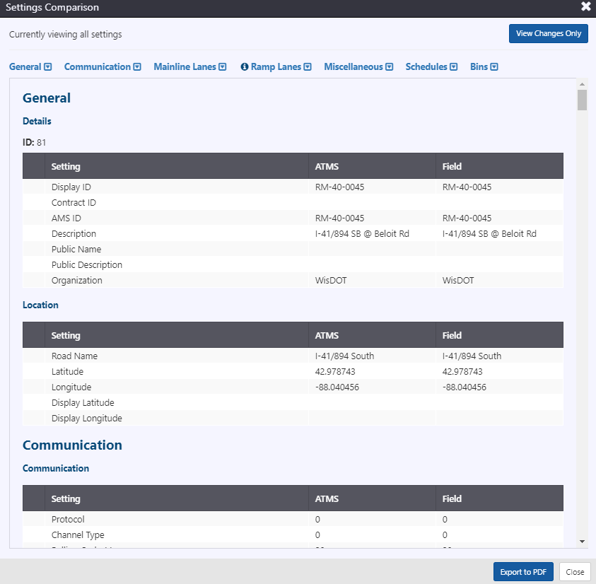
The settings comparison allows users to quickly identify any differences between ramp metering settings as configured in inSIGHT and those that currently exist in the field controller. Users can choose to view all settings, or only those that differ via the button at the top right. Links along the top provide quick navigation to the related sections of the comparison--general, communication, mainline lanes, ramp lanes, miscellaneous, schedules, and bins. Clicking Export to PDF at the bottom will open a print window in the browser, allowing the report to be printed or saved to PDF.
General Information
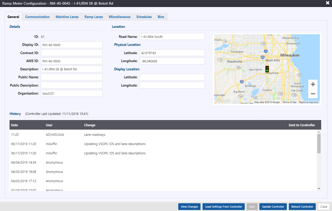
The general information of the device is entered on the 'General' tab, which includes a map presenting the location of the ramp meter, which is updated as ramp meter coordinates are updated. The general information included for a device includes:
- ID: unique ID automatically assigned by the system upon creation
- Display ID: integer ID used for internal referencing of the devices
- Contract ID: string ID used for interfacing with an external system
- AMS ID: string ID used for interfacing with asset management system
- Description: description of the device
- Public Name: name used to refer to the device via ATMS API
- Public Description: description used to refer to the device in ATMS API
- Organization: string to describe what agency is responsible for the sign
- Road name: directional roadway associated with the device. Note, d can also be assigned to the road 'Other' to denote non-agency managed roadways.
- Physical location: latitude and longitude for the physical location of the device
- Display location: latitude and longitude to use as the location for mapping
The tab also includes a history of controller modifications, incorporating comments by the modifier as well as an indication of changes sent to the controller.
Communication
Information needed to determine communication to the sign is grouped into Communication, Connection, and Serial Port Configuration. Communication to ramp meter controllers is managed by the system, and only the IP address and port need to be supplied.
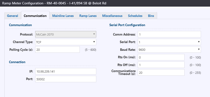
Communication includes:
- Protocol: communication protocol to communicate with the sign. Currently supported protocols include McCain 2070 (v1.8)
- Channel Type: communication type. Currently supported is TCP
- Polling Interval: period of time between successive polls to a device (5-600 seconds)
Settings such as retries and timeout for the ATMS managed globally for the ramp metering service.
Connection information required for a controller includes two items:
- IP: device IP address
- Port: port for device
Serial Port Configuration includes settings in the controller relating to communication:
- Comm Address: Controller address to identify the controller on a communications drop (0-255, 0 is disabled)
- Serial Port: Communications port for serial communication (1-4)
- Baud Rate: Communications port baud rate (1200, 2400, 4800, 9600, 19200, 38400)
- Rts On: Delay between turning on the serial port RTS line and beginning data transmission (0-255 ms)
- Rts Off: Delay between the end of data transmission and turning off the serial port (0-255 ms).
- Setting both Rts On and Off to 0 will keep the RTS line on and eliminate any data transmission delay.
- Communications Timeout: Amount of time that the controller will wait for a valid communications message before dropping any ATMS commanded ramp metering action (0-255 seconds, 0 to disable timeout)
Mainline Lanes
The assignment of individual traffic sensors to mainline lanes is entered into the Mainline Lanes tab. Two sections exist for the settings for mainline lanes and for the mainline detectors, organized by lane.
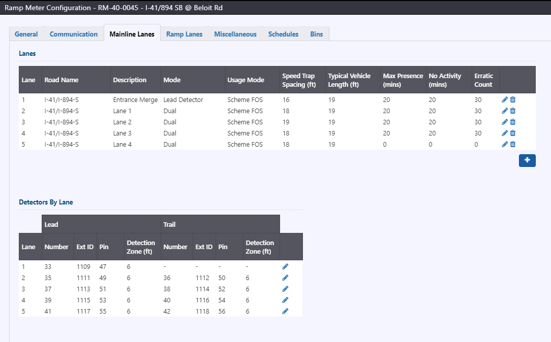
To add a mainline lane, click the button below the table. To edit the settings for a mainline lane, click on the
next to the desired lane. To remove a mainline lane, click on the
button next to the desired lane. Adding or editing a mainline lane will open the Edit Mainline Lane window.
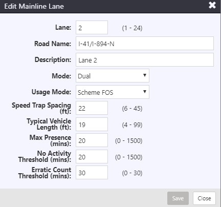
For each mainline lane, the following settings can be configured:
- Description: Text description of the lane
- Mode: Mode of the detector. Other detectors can be enabled or disabled. Demand and passage detectors may be one of the following modes:
- Dual: Both lead and trail detectors are enabled; flow rate and occupancy for traffic responsive operation are calculated from lead detector
- Lead Detector: Only lead detector is enabled; speed/length calculation is disabled
- Trail Detector: Only trail detector is enabled; speed/length calculation is disabled
- Disabled: Detector is disabled
- Usage Mode: The traffic parameters that can be used from the mainline lane to compute traffic responsive levels:
- Disabled: No parameters will be used
- Scheme F: Flow rate only
- Scheme O: Occupancy only
- Scheme FO: Flow rate and occupancy
- Scheme S: Speed only
- Scheme FS: Flow rate and speed
- Scheme OS: Occupancy and speed
- Scheme FOS: Flow rate, occupancy and speed
- Other: Not currently used.
- Speed Trap Spacing: Distance between the lead and trial mainline lane detectors from upstream edge to upstream edge, for speed and length computations (6-45 feet)
- Typical Vehicle Length: Typical vehicle length to assume for a mainline lane. For McCain 2070s, this field is not currently operational.
- Max Presence: Length of time that a detector must remain on to denote as a Max Presence failure (0-1500 minutes, 0 disables monitoring)
- No Activity Threshold: Length of time that a detector must remain off to denote as a No Activity Failure (0-1500 minutes, 0 disables monitoring)
- Erratic Count Threshold: Number of actuation per calculation interval to denote as an Erratic Count failure (0-30 vehicles per calculation interval, 0 disables monitoring)
Detectors for a lane are automatically added and removed when the corresponding mainline lane is added/removed. To edit the settings for the detectors for a lane, click on the next to the desired lane. Editing the detectors for a lane lane will open the Assign Lane Detectors window.
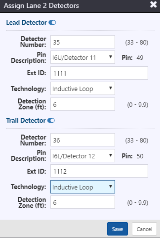
For both lead and trail detectors, the following settings can be configured:
- Enable/disable can be toggled for lead and trail detectors individually. Enabling/disabling mainline detectors will update the mainline lane mode accordingly.
- Detector Number: Detector number for the detector. Numbering is based on the lane number and detector lead/trail:
- Lead detectors are numbered as 2 x lane number plus 31; e.g. lead detector for lane 4 = 2 x 4 + 31 = 39
- Trail detectors are numbered as 2 x lane number plus 32; e.g. trail detector for lane 6 = 2 x 6 + 32 = 44
- Pin Description: The input pin used to connect the detector, as selected from the pre-configured mapping of C1S input pins.
- External Ref ID: The ID for the detector for external systems
- Technology: The type of detection technology used for reference, as selected from the pre-configured list of detection technologies
- Detection Zone: The length of the detection zone for the mainline lane detector, for speed and length computations (0-9.9 feet)
Ramp Lanes
Ramp lanes and dependency groups are found in the Ramp Lanes tab. Ramp lanes are organized by Dependency Group, with each dependency group having settings and a table with the associated ramp lanes.

To add a dependency group, click the Add Dependency Group button below the group settings. To remove a mainline lane, click on the button next to the desired dependency group. The dependency group can be enabled/disabled using the toggle next to the group. Editing settings for the dependency group can be completed inline. The following settings are available:
- Name: Name to refer to the dependency group
- Signal Service Mode: Signal service mode for the dependency group:
- None: No restrictions on lane greens
- MUTX: Mutex, where only one lane in the dependency group may be green at any time
- FXDO: Fixed offset, where the lane must be on for the Green Offset Time before next lane in sequence can go green
- Priority Lane: The number of the ramp lane which will be the priority lane in the dependency group (0-6, 0 to disable). When a priority lane is defined, the red interval on non-priority lanes will be extended by the Red Delay Time if there is demand on the priority lane
- Red Delay Time: The minimum time that a non-priority lane will remain in the red interval when there is demand on the priority lane in the same dependency group (0-5.0 seconds). This delay occurs when there is demand on the priority lane.
- Green Offset Time: The minimum time that a lane must be on before the next lane in sequence can go green (0-10.0 seconds)
A table to the right of the settings lists all ramp lanes associated with the dependency group. To add a ramp lane, click the button below the table. To edit the settings for a ramp lane, click on the
next to the desired lane. To remove a ramp lane, click on the
button next to the desired lane. Adding or editing a ramp lane will open the Ramp Lane window.
The ramp lane window features four tabs: Settings, Detectors, Traffic Responsive, and Outputs. At the top of the ramp lane window are three fields:
- Lane number: number of the lane
- Description: description of the lane
- Sequence: defines the sequence of the lane within the same dependency group, cycling from lowest to highest (1-6)
Ramp Lane Settings
Settings for ramp lane operation and timing intervals are found in the Settings tab. Settings are divided into nine categories.
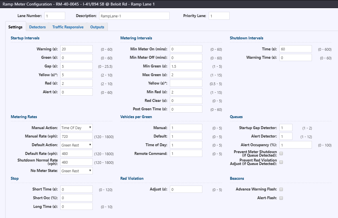
Startup intervals includes timings to govern the start of metering. During startup, a lane will cycle through the following intervals in order: Alert, Warning, Green, Yellow, Red. Settings for startup include:
- Warning: Length of the interval during which the meter is in green rest and advance warning beacon is on (0-60 seconds)
- Green: Length of the interval during which the meter is in green rest and advance warning beacon is on, during which the interval can be terminated by a startup gap on the startup gap queue detector. (0-60 seconds)
- Gap: Length of time during which the absence of actuation on the startup queue detector will terminate the startup green interval (0-25.5 seconds)
- Yellow: Length of time during which the meter signal will be yellow and the advanced warning beacon is on (2-10 seconds, 0 to disable)
- Red: Length of time during which the meter signal will be red and the advanced warning beacon is on (2-10 seconds)
- Alert: Length of time during which the meter will remain dark and advance warning beacon is on (0-60 seconds)
Metering intervals includes timings to govern the normal signal operation, including:
- Min Meter On: Length of time that a meter must remain in metering, once it has started metering(0-60 minutes)
- Min Meter Off: Length of time that a meter must remain non-metering, once it has stopped metering (0-60 minutes)
- Min Green: Minimum length of time that a meter signal must remain in a green state (1-5 seconds)
- Max Green: Maximum length of time that a meter signal may remain in a green state (1-15 seconds)
- Yellow: Length of the yellow interval during normal metering (0.5-5 seconds, 0 to disable)
- Min Red: Minimum length of time that a meter signal must remain in a red state (1-5 seconds)
- Red Clear: Red violation clearance time, i.e. the length of time after the start of a red interval before counting detection as a red violation (0-5 seconds, 0 to disable red light violation detection)
- Post Green Time: Length of the green interval at the end of metering, after the shutdown warning time has elapsed (0-60 seconds)
Shutdown intervals includes timings to govern the end of metering (i.e. when commanded to Dark or Green Rest), including:
- Time: Length of the shutdown metering interval (0-600 seconds)
- Warning Time: Length of the interval after the shutdown time during which the meter signal is green and the advance warning beacon is on (2-10 seconds)
Metering rates includes rates for the meter to apply:
- Manual Action: The metering action when the meter is set to Manual command source. Options include No Change and Local TOD (revert to TOD schedule) in addition to the normal set of metering actions
- Manual Rate: The metering rate to use when the meter is set to Manual command source and the Manual Action is Fixed Rate (120-1800 vph)
- Default Action: The metering action when the meter is set to Default command source
- Default Rate: The metering rate to use when the meter is set to Default command source and the Default Action is Fixed Rate (120-1800 vph)
- Shutdown Normal Rate: The metering rate to use during the shutdown interval (120-1800 vph)
- No Meter State: The state (Daakr or Green Rest) to use when the commanded action is traffic responsive and the Level 1 traffic responsive thresholds have not been met.
Vehicles per green sets the number of requested vehicles to pass during the green and yellow intervals per source (0-5, 0 acting the same as 1).
- Manual
- Default
- Time of Day
- Remote Command
Queues includes settings related to queue detector modification of metering:
- Startup Gap Detector: Denotes which detector to use to detect a startup gap to terminate the Startup Green Interval (1-12, with 1 and 2 being the two detectors associated with ramp lane 1, 3 and 4 being associated with ramp lane 2, etc.)
- Alert Detector: Denotes which detector to use to detect a congested lane condition for the ramp lane for the controller status
- Alert Occupancy: The occupancy threshold that must be exceeded on the Alert Queue Detector to detect a congested lane condition for the queue alert in controller status (0-100)
- Prevent Meter Shutdown (if Queue Detected): Queue vs. shutdown flag; if enabled the presence of a queue on associated queue detectors will prevent the meter from shutdown metering until the queue has dissipated
- Prevent Red Violation Adjust (if Queue Detected): Queue vs. violation flag; if enabled the presence of a queue on associated queue detectors will prevent the meter from making red violation timing adjustments
Stop includes settings related to identifying if a short stop condition is detected, in order for the controller to place a demand on the lane to terminate the red interval, as well as the setting to extend the red interval if a long stop condition is detected:
- Short Time: Length of time during a red interval without demand to assume short stop condition (0-99.9 seconds, 0 to disable short stop detection logic)
- Short Occ: Minimum occupancy threshold on queue detector (configured to be used to identify short stop condition) to assume short stop condition (0-100)
- Long Time: Length of time added to the red interval if a long stop condition is detected, i.e. if the passage detector is actuated at the end of the timed red interval (0-25.5 seconds)
Red violation includes the adjust time, i.e. the amount of time to extend the red interval if a vehicle is detected on the passage detector after the red clear time has passed.
Beacons indicates how the beacons should operate:
- Advance Warning Flash: When advance warning beacons are on, if checked beacons will flash at 1Hz instead of solid on
- Alert Flash: during the startup alert interval, if checked, beacons will flash at 1Hz instead of solid on
Ramp Lane Detectors
Sensor assignments for ramp lanes, including queue detector settings and thresholds are entered into the Detectors tab.
Demand/Passage/Other Detectors
Demand, passage, and other detectors are configured at the top of the window. Fields allow for configuration of each of these detectors.
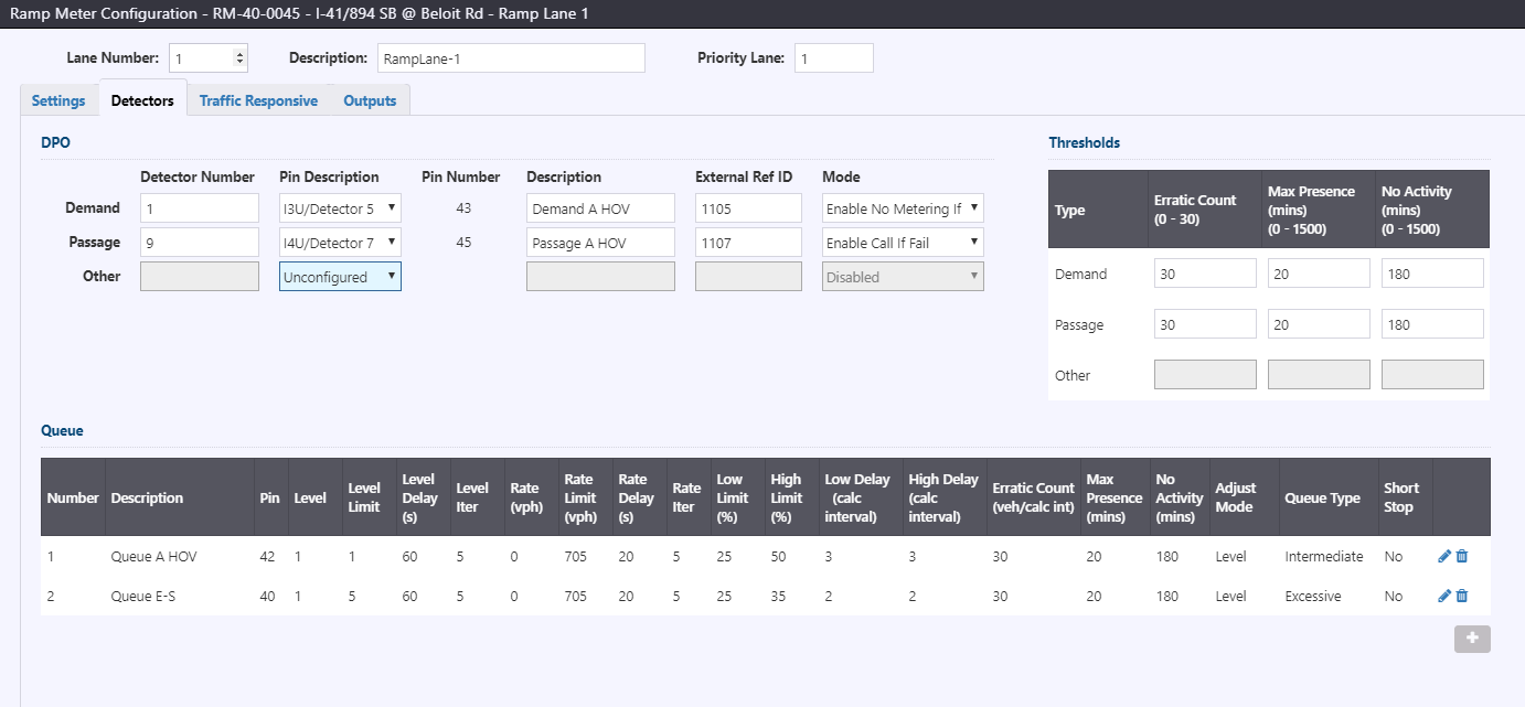
Settings for the demand, passage and other detectors include:
- Detector Number: Detector number for the detector. Numbering is based on the lane number and detector type:
- Demand detector number is the ramp lane number (1-8)
- Passage detector number is the ramp lane number plus 8 (9-16)
- Other detector number is ramp lane number plus 80 (81-88)
- Pin Description: The input pin used to connect the detector, as selected from the pre-configured mapping of C1S input pins.
- Description: Text description of the detector
- External Ref ID: The ID for the detector for external systems
- Mode: Mode of the detector. Other detectors can be enabled or disabled. Demand and passage detectors may be one of the following modes:
- Recalled: Detector will have a constant call for demand/passage
- Enable Call If Fail: Demand/passage will be called when the detector is actuated, and a constant call will be placed if detector fails
- Enable No Call If Fail: Demand/passage will be called when the detector is actuated, detector failure will not change operation
- Disabled: Detector is disabled
Thresholds for the demand, passage, and other detectors can be entered in the table to the right. Threshold settings govern the failure diagnostics of the detector:
- Erratic Count: Number of actuation per calculation interval to denote as an Erratic Count failure (0-30 vehicles per calculation interval, 0 disables monitoring)
- Max Presence: Length of time that a detector must remain on to denote as a Max Presence failure (0-1500 minutes, 0 disables monitoring)
- No Activity: Length of time that a detector must remain off to denote as a No Activity Failure (0-1500 minutes, 0 disables monitoring)
Queue Detectors
Queue detectors are listed in a table below DPO detectors. Setting values are summaries in this table. To add a queue detector, click the button below the table. To edit the settings for a queue detector, click on the
next to the desired queue detectors. To remove a queue detector, click on the
button next to the desired queue detector.
Adding or editing a queue detector will open the New/Edit Queue Detector window.
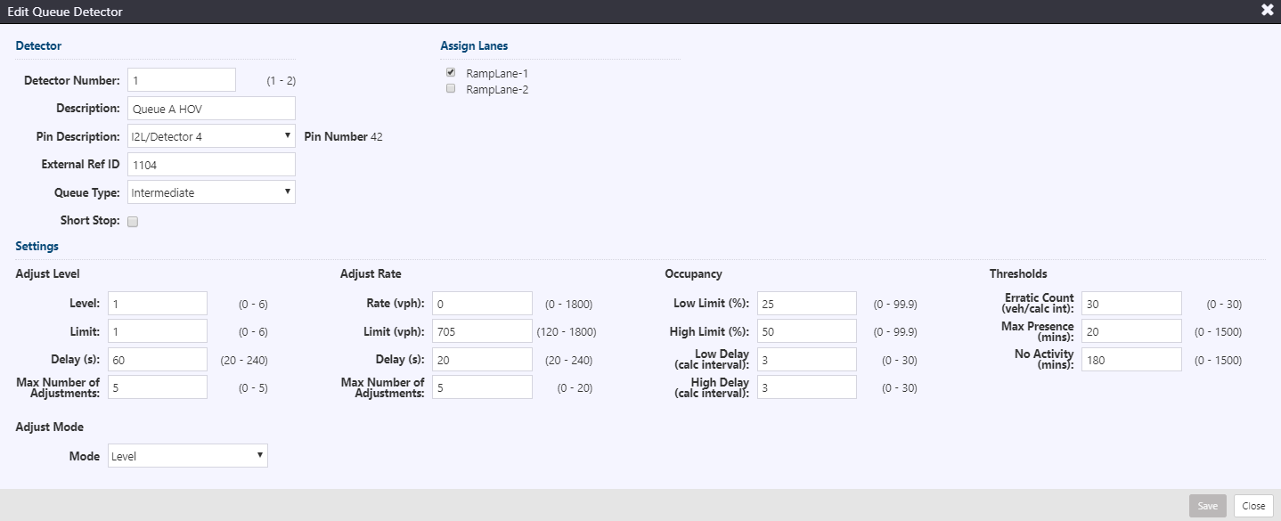
The queue detector settings include Detector, Assign Lanes, and Settings sections.
Under Detector, settings include:
- Detector Number: Detector number for the queue detector (1 or 2)
- Description: Text description of the queue detector
- Pin Description: The input pin used to connect the detector, as selected from the pre-configured mapping of C1S input pins.
- External Ref ID: The ID for the detector for external systems
- Queue Type: The type of queue associated with the detector. Values include Intermediate, Excessive, and Other. For the McCain 2070s, Intermediate and Excessive operate the same and Other disables the queue detector.
- Short Stop: The ability of the queue detector to cause a short stop condition of its corresponding lane. Check to enable.
Assign Lanes indicate which lanes the queue is assigned to for queue overrides. Check to enable a lane to be included in queue override operations for this detector
The Settings section includes settings that govern queue override operations. Settings are grouped into Adjust Level, Adjust Rate, Occupancy, Thresholds, and Adjust Mode.
Adjust Level settings are used when the Adjust Mode is set to Level. Settings include:
- Level: Number of levels that will be subtracted each adjustment when a queue is detected, or added when the queue has dissipated (0-5, 0 disables adjustments)
- Limit: Minimum level to use in the rate table (0-5, 0 disables adjustments)
- Delay: Length of time between adjustments (20-240 seconds)
- Max Number of Adjustments: Also known as Adjust Iters, this is the maximum number of adjustments that can be made during the life of a queue (0-5, 0 disables adjustments)
Adjust Rate settings are used when the Adjust Mode is set to Rate. Settings include:
- Rate: Volume per hour to be subtracted each adjustment when a queue is detected, or added when the queue has dissipated (0-1800 vph, 0 disables adjustments)
- Limit: Maximum rate to use in adjustments (120-1800 vph)
- Delay: Length of time between adjustments (20-240 seconds)
- Max Number of Adjustments: Also known as Adjust Iters, this is the maximum number of adjustments that can be made during the life of a queue (0-5, 0 disables adjustments)
Occupancy settings provide high and low thresholds for defining a queue:
- Low Limit: Maximum occupancy threshold before a queue can be cleared (0-99.9%)
- High Limit: Minimum occupancy threshold before a queue can be defined (0-99.9%)
- Low Delay: Number of calculation intervals required at occupancy below Low Limit to clear a queue (0-30 calculation intervals)
- High Delay: Number of calculation intervals required at occupancy above High Limit to define a queue (0-30 calculation intervals)
Threshold settings govern the failure diagnostics of the detector:
- Erratic Count: Number of actuation per calculation interval to denote as an Erratic Count failure (0-30 vehicles per calculation interval, 0 disables monitoring)
- Max Presence: Length of time that a detector must remain on to denote as a Max Presence failure (0-1500 minutes, 0 disables monitoring)
- No Activity: Length of time that a detector must remain off to denote as a No Activity Failure (0-1500 minutes, 0 disables monitoring)
Adjust Mode denotes the logic to adjust the metering rate in response to the presence of a queue:
- Level: Metering will be adjusted by level; and only if meter is in traffic responsive mode.
- Rate: Metering will be adjusted by rate.
- Other: Metering will not be adjusted.
Ramp Lane Traffic Responsive
For each ramp lane, the mainline lanes to be included in traffic responsive operation mode and the lane rate table are entered into the Traffic Responsive tab.
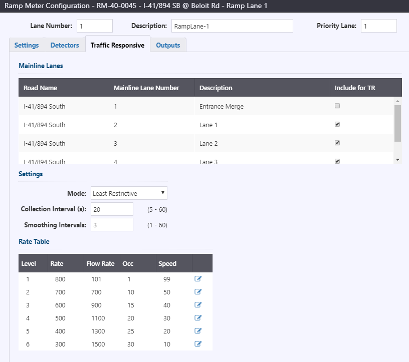
The Mainline Lanes section lists all mainline lanes in the controller. The 'Include for TR' checkbox is used to select which mainline lanes should be used for traffic responsive metering.
The Settings section includes metering mode, collection interval, and smoothing interval. Mode options include:
- Most Restrictive: Highest metering level of the metering levels calculated from the smoothed average mainline average volume, occupancy, and speed.
- Least Restrictive: Lowest metering level of the metering levels calculated from the smoothed average mainline volume, occupancy, and speed.
- Smoothed Volume: Metering level based on the smoothed average mainline volume.
- Smoothed Occupancy: Metering level based on the smoothed average mainline occupancy.
- Smoothed Speed: Metering level based on the smoothed average mainline speed.
The collection interval and smoothing intervals are used to identify the length of the calculation interval (5-60 seconds) for detector volume/occupancy/speed smoothing. The smoothing intervals (1-60) denotes the number of calculation intervals to be used for smoothing mainline station averages.
The Rate Table section denotes the rate levels for the ramp lane. To edit a level of the rate table, click the appropriate level.
- Level: Number of the traffic responsive level (1-6, not editable).
- Rate: Base-metering rate used by the lane (120-1800 vph, decreasing from rates 1 to 6)
- Flow Rate: Flow rate minimum threshold to select the level for traffic responsive metering (0-3000 vph, increasing from rates 1 to 6)
- Occ: Occupancy minimum threshold to select the level for traffic responsive metering (0-100% increasing from rates 1 to 6)
- Speed: Speed maximum threshold to select the level for traffic responsive metering (0-99 mph decreasing from rates 1 to 6)
Ramp Lane Outputs
For each ramp lane, output signal settings are entered into the ramp lane 'Outputs' tab.
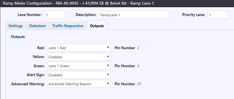
Output settings include
- Red: The output pin to be activated when the metered lane is red; as selected from the pre-configured mapping of C1S/C11S output pins.
- Yellow: The output pin to be activated when the metered lane is yellow; as selected from the pre-configured mapping of C1S/C11S output pins.
- Green: The output pin to be activated when the metered lane is green; as selected from the pre-configured mapping of C1S/C11S output pins.
- Alert Sign: The output pin to be activated when a congested lane condition is detected; as selected from the pre-configured mapping of C1S/C11S output pins.
- Advanced Warning: The output pin to be activated when the lane is being metered, as selected from the pre-configured mapping of C1S/C11S output pins.
Miscellaneous
Controller outputs and other settings are entered into the 'Miscellaneous' tab. Settings are divided into three sections: Outputs, Alarm Inputs, and Miscellaneous.
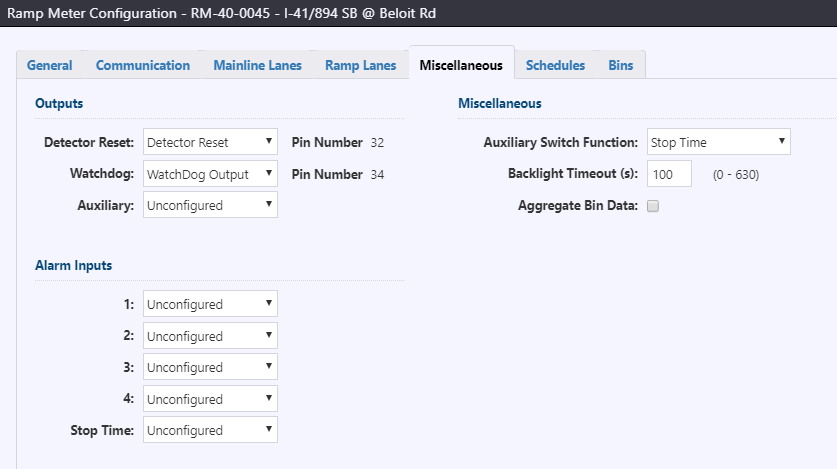
Outputs defines the output pins to be used, as selected from the pre-configured mapping of C1S/C11S pins.
Alarm Inputs defines input pins to be used for alarms, as selected from the pre-configured mapping of C1S/C11S pins.
Miscellaneous settings include the function to activate when the aux switch is turned on (None, Stop Time, or Detector Reset), the Backlight Timeout in seconds, and a checkbox to aggregate total length classification for all lanes for a direction instead of storing by lane.
Schedules
The configuration for day of week and time of day operation, as well as holidays, is entered into the 'Schedules' tab.
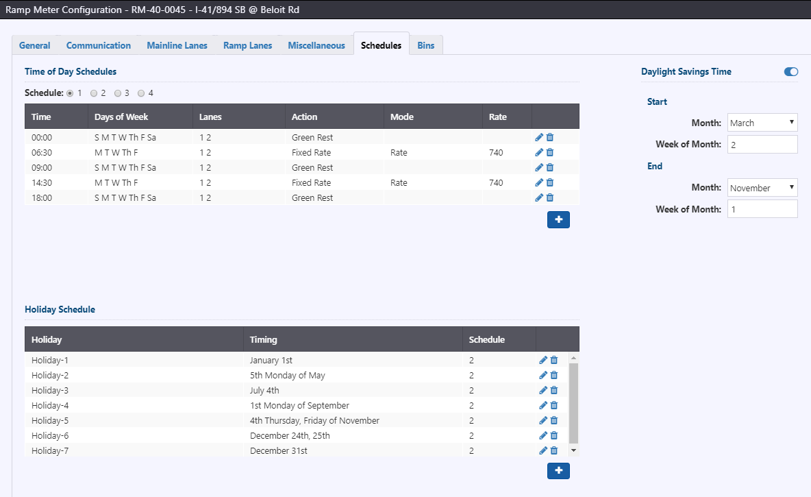
Three sections exist in this tab: time of day schedules, holiday schedule, and daylight savings time.
Time of Day Schedules
Time of day schedule entries are listed in a table. The schedule (1, 2, 3 or 4) can be selected above the table. To add a schedule entry, click the button below the table. To edit a schedule entry, click on the
next to the entry. To remove a schedule entry, click on the
button next to the desired queue detector.
Adding/editing a schedule entry will open the Add/Edit Schedule window.
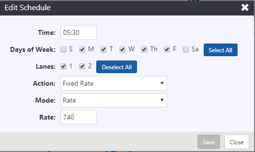
Settings for a schedule entry include the following:
- Time: Time when the schedule action should be observed (0:00-23:59)
- Days of Week: Days of the week when the schedule action should be observed.
- Lanes: Ramp lanes that should observe the schedule action
- Action: metering action to follow at the scheduled time. Actions include Disabled, Dark, Green Rest, Fixed Rate, Traffic Responsive, and Emergency Green.
- Mode: Level to use for fixed rate metering (Rate for specific value, or Level 1-6 to follow rate table rates). Only shown if Action is set to Fixed Rate
- Rate: Rate for fixed rate metering (120-1800 vph). Shown if Mode is set to Rate
Holiday Schedule
Holiday entries are listed in a table below the TOD schedules. To add a holiday, click the button below the table. To edit a holiday, click on the
next to the desired holiday. To remove a holiday, click on the
button next to the desired holiday.
Adding/editing a holiday entry will open the Add/Edit Holiday window.
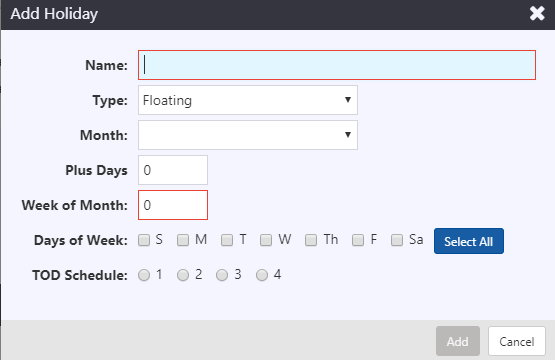
Settings for a holiday entry include the following:
- Name: Name to refer to the holiday
- Type: Toggle between Fixed Date and Floating holiday types
- Month: Month for the holiday (Jan to Dec)
- Date: Date in the month for the holiday (1-31, only for fixed date holidays)
- Plus Days: Number of days to extend the holiday beyond the first date (0-255)
- Week of Month: Week of the month when the holiday should occur (1-5, only for floating holidays. 5 denotes last week of month)
- Days of Week: Day(s) of the week when the holiday is valid
- TOD Schedule: Sets the TOD table that should be active when the holiday is active
Daylight Savings Time
Daylight savings time settings include a toggle to enable/disable changes for daylight savings time, as well as settings to denote when to Start daylight savings time (transition forward one hour, i.e. spring) and End DST (backward one hour, i.e. fall):
- Month: Month for the change
- Week of Month: Week (Sunday) of the month when the transition should occur (1-5, 5 denoting the last Sunday of the month)
The transition occurs at Sunday 2:00 a.m.
Bins
Configuration of traffic bins for classification counts are entered into the 'Bins' tab. Up to two directions can be recorded. When a lane is included in a directional bin, detection on that mainline lane is counted in the bin. Length bin counts are reset each calculation period

For each direction, two items can be configured: direction of traffic, and mainline lanes to include in the directional bin. Mainline lanes are automatically added/removed from the available list based on the mainline lane configuration.
The Bins table section denotes the length and speed bins for a direction. To edit the length or speed bins, click the button for that row.
Global Configuration Settings
The service parameters are used to globally in the service. Please contact Arcadis support to update these values.
| PARAMETER | DESCRIPTION |
|---|---|
| PollingIntervalInMs | Polling interval to maintain communication with the controller, to ensure remote commands are not released |
| PollingApplicableRangeInMs | This value ensures we don't over-poll devices - after a poll occurs any subsequent poll request within this time range will be ignored. It is recommended that this be set relatively short. |
| FailedPollRetryDelayInMs | This is the amount of time in milliseconds that the system will wait after a failed poll to retry communication. |
| MaxFailedPollAttempts | Number of failed poll attempts before communications failure |
| MaxFailedRetryIntervalInSec | Time interval in seconds between retrying after a failed poll |
| PeriodicDateTimeSyncInMins | Time interval in minutes for periodic update of controller time |
| FullStatusPollRefreshIntervalInMn | Under normal circumstances, the driver will short-poll and determine when a full status poll is required; this interval adds a full status poll at a regular interval, regardless of the result of the short status poll. 0 to disable. |
| DateTimeSyncDriftRangeInSec | Time interval in seconds of allowable drift |
| BulkUpdateIntervalInSec | This is used to "batch" the standard status updates sent through the hub, to reduce the frequency of updates and eliminate the issue of receiving individual status updates for each and every device, which bogs down the user interface. The larger the value, the longer updates are delayed to the user interface. The shorter the value, the more frequent updates need to be processed by the user interface and too short a value can result in degraded performance in the UI. |
| ConfigRefreshIntervalInMn | Time interval in minutes for periodic update of field configuration from controller configuration |
| UseFieldChangedFlagToRefreshConfig | True/false flag to refresh field configuration from controller configuration on detection of change |