Travel Time
Travel times are calculated for a set of configured routes using traffic data from all available sources including physical detectors, Bluetooth data and probe data from external vendors. The computed travel times are disseminated to stakeholders using:
- Dynamic Message Signs (DMS)
- API or XML data feed
- Highway Advisory Radio (HAR)
- The ATMS User Interface (UI)
General Concepts
Data Sources
There are two general types of traffic data sources: point sources and probe sources
- Point sources include microwave detectors, induction loops, pucks and acoustic detectors. They typically measure traffic volume, occupancy, and speed, and can collect data for both directions of travel at a given location on the roadway
- Probe sources include license plate readers, Bluetooth detectors, fleet trackers and commercial services such as TomTom, Inrix and HERE. These sources typically provide measured travel times over a distance, which is equivalent to average speed along the distance.
Virtual Detection Station (VDS)
A VDS aggregates data for all lanes in a given direction of travel at a point on the roadway. Lanes monitored by Point sources are assigned to VDS, and the VDS data is used in later travel time calculations. A VDS can be associated with lanes from one or more Point sources.
Segments
A Segment defines a section of directional roadway. Segments are specified by a start coordinate and end coordinate on a roadway.
Source Segments
Data from the various sources of traffic is associated with a segment. For probe detectors the segment is explicitly defined by the source; for point detectors the segment is configured or calculated for each VDS. For example, VDS segments may be calculated from midpoint to midpoint of VDS on the road. Segments from different traffic data sources may overlap.
Application Segments
An application segment is a roadway segment that the ATMS is required to compute data for. There are multiple types of application segments managed within the ATMS.
- Travel Time Segment : a portion of a travel time route
- Heat Map Segment : used for display of traffic data heat maps in the UI
- Published Segment : Exposed to external systems using either an API or file transfer mechanism
Travel Time Routes
Route Definition
A route is defined as a collection of Travel Time application segments. A route can traverse multiple roads, including the case of a detour off and then back onto the starting road. Routes will have at least as many segments as distinct roadways that the route traverses, with additional segments required for non-contiguous stretches of the same roadway.
In addition to route names, travel time routes include the following configurable parameters:
- Minimum Travel Time : This is the minimum time the ATMS will disseminate for a route. If the computed travel time for a route is less than this value, the minimum time will be substituted prior to pushing this information to DMS, HAR or external systems. This is typically computed based on posted speeds but can be configured to be a longer time.
- Maximum Travel Time : If the route travel time exceeds this value, the route will be marked as invalid, and will no longer be included in DMS and HAR messaging.
Alternate Routes
It is possible to configure inSIGHT to automatically switch to comparative/alternate route travel times when an alternate route has the same or faster travel times. The alternate route will display on a sign in cases where the travel time for a given alternate route is less than that of one of the sign’s normal routes by a configurable amount of time, and this condition persists for a configurable number of calculation intervals.
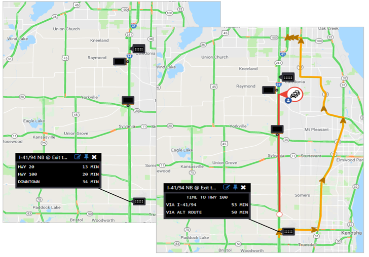
For example:
Routes A, B and C are configured on the sign, resulting in a typical message of:
Destination A - 13 mins
Destination B - 20 mins
Destination C - 34 mins
Route B has been configured to have an alternate route (Route D), and the travel time for route D is more than a configurable (for the sign/route) number of minutes lower than that of route B for a configurable number of consecutive intervals. The system would then display a message as follows:
Destination B
Via Path B - 53 mins
Via Path D - 50 mins
When the travel time for route D is no longer less than a configurable number of minutes lower than that of route B for a configurable number of consecutive intervals, the system would revert back to its normal signing behavior For the alternate route, a user can configure:
Whether or not to enable alternate route signing for the sign
The minimum required difference in travel times between the alternate route and the base route
The alternate travel time route to use
The destination name of the alternate route
The path of the alternate route (ex/ 'VIA US-xx)
The normal route to compare it to (of the routes already configured for the sign)
Travel Time Calculation
The travel time for a route is the sum of the travel times of its application segments. The travel time for each segment is computed using the following steps:
- Determine which Source segments overlap the route, and the length of the portion of each source segment that should apply to the route. When segments from different source types overlap each other, the system selects the highest priority source that is reporting data for the overlapping portion. The priorities are typically configured to use DOT sources first, followed by external information sources. For example: Physical Detectors Bluetooth data Probe data.
- Compute the average speed of the segment using a weighted harmonic mean. The weighting for each source segment is the length of that source segment that applies to the travel time segment. The weighted harmonic mean only accounts for portions of the travel time segment that are covered by traffic data reported in the current collection interval – if only 9 miles of a 10 mile route have traffic data, the average speed that is computed over the 9 miles with data is assumed to apply to the full route.
The formula for the weighted harmonic mean is
where w is the length of the source segment to apply, and x is the speed reported by the source for that segment.
- Compute the travel time of the segment as Segment Length ÷ Segment Speed
A number of values are calculated for each route, which can be seen in the TT Route Data list:
- Length
- Hist TT : historical travel time, based on historical average travel times recorded in the system for the same day of week, month, and 5 minute interval.
- Calc TT : raw system-calculated travel time
- Min TT : minimum travel time, as configured for the route
- Smoothed TT : travel time after smoothing
- Delay : percent delay between smoothed time and minimum time
- Mode : current mode of the route, either Automatic or Disabled.
- Valid : validity of the route, either Yes, No, or Suspect. Suspect routes are those where one or more segments are invalid however the route as a whole is valid.
- Use : methods for disseminating the travel time, including sign, api, and har.
Travel time routes are colored as follows:
- Red if route is invalid
- Green if calculated travel time is below minimum travel time
- Black if route is valid and above minimum travel time
Selecting Source Segments
In the diagram below, a 10 mile route segment is covered by data from physical detectors (VDS Data), a Bluetooth provider, and probe data from a 3rd party source. VDS data is considered to be the best/highest priority data, followed by Bluetooth data, followed by probe data. In this case, the segment speed would be calculated using data from VDS segments 1, 2, 3, 4 and 5, as well as Bluetooth segment 4.
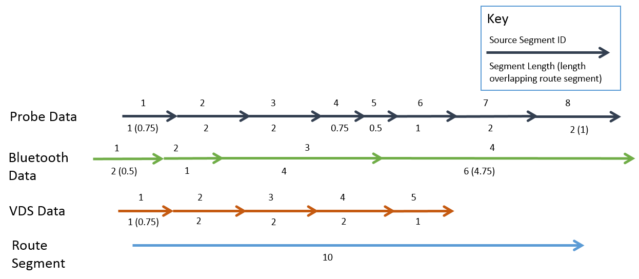
The length of each segment to apply would be as follows:
| SOURCE TYPE | SEGMENT | LENGTH TO APPLY | NOTE |
|---|---|---|---|
| VDS | 1 | 0.75 | The length of the source segment that overlaps the travel time segment |
| VDS | 2 | 2 | |
| VDS | 3 | 2 | |
| VDS | 4 | 2 | |
| VDS | 5 | 1 | |
| Bluetooth | 4 | 3.75 | The length of the source segment that overlaps with the route, less the length of the source segment that overlaps higher priority VDS segments 4 (partial) and 5. |
In the diagram below, no data is available for VDS segment 3 (this could be due to a device or communication failure).
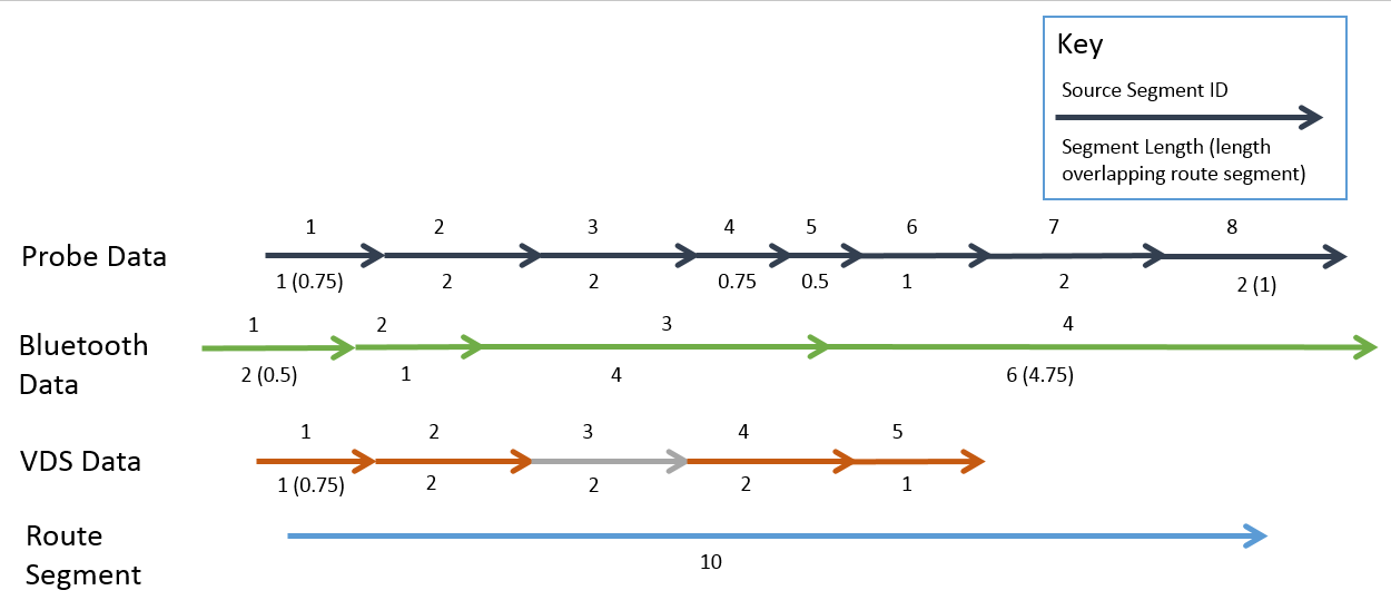
In this case, the length of each segment to apply would be as follows:
| SOURCE TYPE | SEGMENT | LENGTH TO APPLY | NOTE |
|---|---|---|---|
| VDS | 1 | 0.75 | The length of the source segment that overlaps the travel time segment |
| VDS | 2 | 2 | |
| VDS | 4 | 2 | |
| VDS | 5 | 1 | |
| Bluetooth | 3 | 2 | The length of the source segment that overlaps the route, and VDS segment 3 (for which there is no data available) |
| Bluetooth | 4 | 3.75 | The length of the source segment that overlaps with the route, less the length of the source segment that overlaps higher priority VDS segments 4 (partial) and 5. |
Travel Time Validation
In addition to validating the reported travel time for each route against the maximum allowable time, the ATMS validates routes based on the percentage of the route length that is covered by valid Travel Time segments. If the total length covered by valid segments divided by the total route length is less than a configurable percentage, the route is considered invalid and will not be included in any dissemination of travel times. This percentage is a single configuration value that applies to all routes.
Individual Travel Time segments are considered valid if a minimum required percentage of the segment is covered by valid traffic data in a given interval. The percentage of a segment that must be covered by valid data is a single configuration value that applies to all segments.
Travel Time Route Configuration
Creation and management of a travel time route can be completed by via UI. Simply click on the gear icon on the left top corner of the ATMS screen and select the Travel Time Routes.
From the Route Configuration screen, the following actions are possible:
- Edit existing route
- Delete existing route
- Create new route from existing
- Add new route using the add route button.
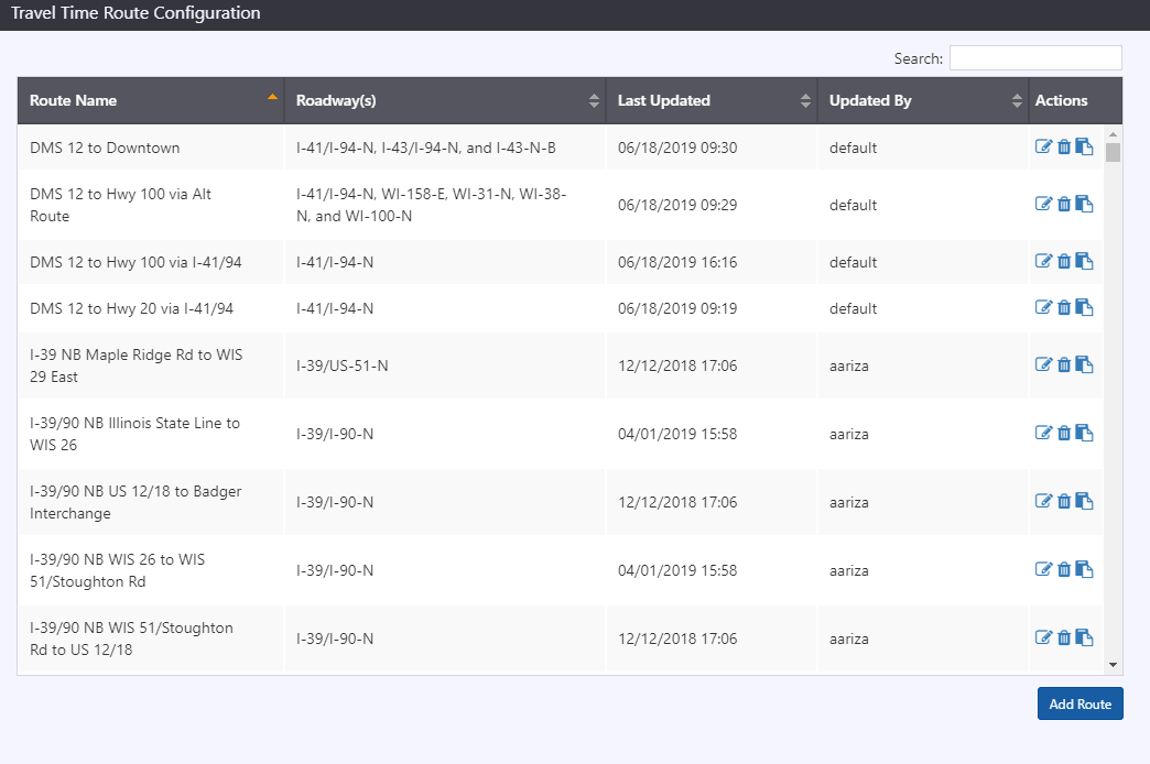
Travel time routes consist of a route name, minimum and maximum travel times, the option to include the route in API, and a series of waypoints and derived segments.
Waypoints are added to define a route by right-clicking on the map and selecting the associated roadway. The first waypoint denotes the start of the travel time route. Adding a second or subsequent waypoint creates one or more segments for each of the roadways traversed between each subsequent waypoint.
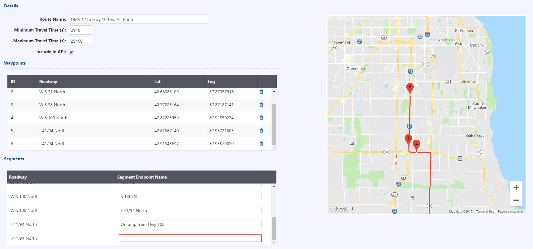
Waypoints will be added sequentially, and cannot be inserted between existing waypoints. Removing a waypoint will cause the shortest route to be recalculated between the previous and next waypoints.
For each segment created, a segment endpoint name field is provided allow a description of each segment. This field is used in the segment list.
Travel Time Signing
Sign Assignment
Signs are configured to receive travel time messages by assigning one or more travel time routes to them. Within the System Parameters, there is a Travel Time Signing Configuration item which provides a list of all signs configured with travel time messaging within the system. From here, a sign can be configured for travel time messaging, or existing configuration can be modified.

For each route, a user can configure:
- The route destination for use in signing
- The route path that can optionally be used in messaging (ex/ 'VIA US-xx)
- The priority of the route, which in cases where there are more routes configured for the sign than will fit in any message templates for that sign, which routes will be included
Up to six routes can be configured for each sign. Routes will appear on a sign based on the order they are entered, i.e. route 1 will be the first route listed on a sign. Priority values dictate which routes are included on a sign, independent of order. For example, if there are four routes valid, but route 1 has a priority value of 4 and only three routes can fit on the sign, the routes to appear on the sign would be 2, 3 and 4.
A setting also exists to allow/disallow duplicate travel times on a sign to control if a sign would include equal travel times to two different destinations or not.
Alternate routes can also be configured for a sign. An alternate route can be enabled, and based on the minimum travel time difference entered, the system will switch to alternate travel time messaging if that difference threshold has been met for a configurable number of consecutive cycles. For the alternative route, a user can configure:
- Alternate route to use
- The route destination for use in signing
- The route path that can optionally be used in messaging (ex/ 'VIA US-xx)
- The route to compare with the alternate route.
Alternate route messaging will occur where the alternate travel time is more than the min TT difference faster than the normal travel time, for a configurable consecutive number of calculation intervals. Alternate route signing remains activated until the travel time difference falls below the min TT difference for a configurable consecutive number of calculation intervals.
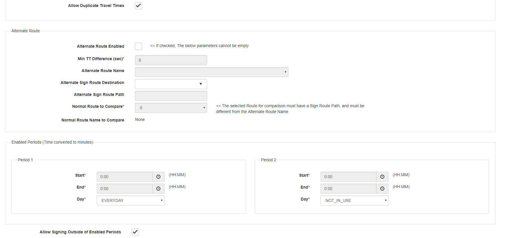
It is possible to define up to two different time periods during which a sign should display travel time messages. These periods are configurable by sign, and can apply to all days, weekdays or weekends and holidays. For example, a sign could be set to display travel times during the AM and PM peak periods on weekdays. The start and end time of each period must be on the same day.
It is possible to configure each sign to display travel time messages outside of the regularly scheduled periods. Signing outside of enabled periods will occur (in configured) in cases where the current travel time delays exceeds the delay percent threshold for a configurable consecutive number of calculation intervals. Signing remains activated until the travel time delays fall below the no delays percent threshold for a configurable consecutive number of calculation intervals.
Message Templates
Travel time messages are generated using message templates configured for each sign display format. They can include a combination of static text and variables to populate. Message templates are generated in a sequential order—if the first template in the sequence fails to generate (for example if a variable is missing or the message length exceeds the width of the sign), the system will attempt the next message template in the sequence.
The templates/message types that can be used for travel times are as follows:
| MESSAGE TYPE | DESCRIPTION |
|---|---|
| TT | Template to be used when all travel time routes on the sign are neither above nor below the Upper and Lower TT Signing Ratios, respectively |
| LONG TT | Template to be used when all travel time routes on the sign are above the Upper TT Signing Ratio |
| SHORT TT | Template to be used when all travel time routes on the sign are below the Lower TT Signing Ratio |
| MIXED TT | Template to be used when not all travel time routes are above or below either the Upper or Lower TT Signing Ratios, respectively |
| TT ALT ROUTE | Template to be used when the alternate route is more than the min TT difference faster than the normal travel time |
| [Next Long TT Route TEXT] | Compressed template that defines what text should be displayed for a route when the route is above the Upper TT Signing Ratio |
| [Next Medium TT Route TEXT] | Compressed template that defines what text should be displayed for a route when the route neither above the Upper TT Signing Ratio nor below the Lower TT Signing Ratio |
| [Next Short TT Route TEXT] | Compressed template that defines what text should be displayed for a route when the route is below the Lower TT Signing Ratio |
Compressed templates are available to use as variables in a template and rendered when the system generates the template message. The variables that can be included in templates are as follows:
| VARIABLE | DESCRIPTION |
|---|---|
| [Next TT destination] | Populated with destination of the first/next valid route that is assigned to the sign |
| [Next TT path] | The path description (ex/ “VIA US-xx”) of the first/next valid route |
| [Next TT range] | The travel time, or travel time range of the first/next valid route |
| [Dist to next TT destination] | The distance to the first/next valid route |
| [route 1 TT range] | The travel time for route 1; used for hybrid travel time signs where the position of the travel time is fixed relative to the static text on the sign |
| [route 2 TT range] | The travel time for route 2; used for hybrid travel time signs where the position of the travel time is fixed relative to the static text on the sign |
| [route 3 TT range] | The travel time for route 3; used for hybrid travel time signs where the position of the travel time is fixed relative to the static text on the sign |
| [route 4 TT range] | The travel time for route 4; used for hybrid travel time signs where the position of the travel time is fixed relative to the static text on the sign |
| [route 5 TT range] | The travel time for route 5; used for hybrid travel time signs where the position of the travel time is fixed relative to the static text on the sign |
| [route 6 TT range] | The travel time for route 6; used for hybrid travel time signs where the position of the travel time is fixed relative to the static text on the sign |
| [Alternate route TT destination] | Alt route variable: The destination of the alternate route |
| [Alternate Route TT path] | Alt route variable: The path description (ex/ 'VIA US-xx') of the alternate route |
| [Alternate Route TT range] | Alt route variable: The travel time, or travel time range of the alternate route |
| [Normal Compared Route TT range] | Alt route variable: The travel time, or travel time range of the base or normal route |
| [Normal Compared Route TT path] | Alt route variable: The path description (ex/ 'VIA US-xx') of the base or normal route |
| [Next Long TT Route TEXT] | Compressed template that defines what text should be displayed for a route when the route is above the Upper TT Signing Ratio |
| [Next Medium TT Route TEXT] | Compressed template that defines what text should be displayed for a route when the route neither above the Upper TT Signing Ratio nor below the Lower TT Signing Ratio |
| [Next Short TT Route TEXT] | Compressed template that defines what text should be displayed for a route when the route is below the Lower TT Signing Ratio |
| [INDICATE ROUTE CLOSURE] | If the travel time route is invalid due to a closure on the route, a configurable string will replace the TT range instead of skipping this route |
| [INDICATE ROUTE INVALID] | If the travel time route is invalid for reasons other than a closure on the route, a configurable string will replace the TT range instead of skipping this route |
| [Right->] | Used to justify text—text to the left of the tag will be left justified on the sign, and text to the right of the tag will be right-justified. If no '[Right->]' tag is used in a line, the text will be centered. |
| [OPTIONAL LINE] | Indicates that a given line of the template is optional. If the template includes space for three routes, and two are marked as optional, if there is only one valid route for the sign, a single line message will be sent. |
| [cfR,G,B] | NTCIP MULTI tag used to specify the color for the text that follows, where R, G, and B are replaced with the specific RGB values |
For example, the template:
Line 1: [TO next TT destination]
Line 2: [dist to next TT destination] MILES
Line 3: [next TT range] MIN
Will display the message:
The template:
Line 1: Destination [RIGHT->] Travel Time
Line 2: [TO next TT destination][RIGHT->][next TT range] MIN
Line 3: [TO next TT destination][RIGHT][next TT range] MIN
Will display the message:
The template:
Line 1: [TO alternate route TT destination] VIA
Line 2: [Normal Compared Route TT path][Right->][Normal Compared Route TT range] MIN
[Alternate Route TT path][Right->][Alternate Route TT range] MIN
Multiple nested templates can be placed on the same line, and the system will choose the appropriate version to use. For example, a template that contains [Next Long TT Route TEXT][Next Medium TT Route TEXT] [Next Short TT Route TEXT] on the same line will only render one travel time route on that line.
Travel Time Display Bins
Travel times are computed internally in the ATMS as an exact number (minutes and seconds). Travel times disseminated via DMS and HAR may be formatted as ranges. This is intended to:
- Indicate that travel times are approximate
- Account for the fact that conditions may change while drivers are en route, and are more prone to change over longer routes
- Reduce fluctuation in the posted/broadcast travel times
The ranges to display, and the associated computed travel time ranges are configurable. An example set-up follows.
| COMPUTED TRAVEL TIME | DISSEMINATED TRAVEL TIME |
|---|---|
| <=3.5 minutes | 3 MIN |
| >3.5 minutes and <= 4.5 minutes | 4 MIN |
| >4.5 minutes and <= 5.5 minutes | 5 MIN |
| >5.5 minutes and <= 7.5 minutes | 6 – 8 MIN |
| >9.5 minutes and <= 11.5 minutes | 10 – 12 MIN |
| >11.5 minutes and <= 14.5 minutes | 12 – 15 MIN |
| >14.5 minutes and <= 17 minutes | 15 – 18 MIN |
| >17 minutes and <=19.5 minutes | 15 – 20 MIN |
| >19.5 minutes and <=24.5 minutes | 20 – 25 MIN |
| >24.5 minutes and <=30 minutes | 25 – 30 MIN |
| >30 minutes | INVALID |
Global Configuration Settings
TRAF
Traf parameters are used to determine validity of travel time segments, as well as probe data segments.
| PARAMETER | DESCRIPTION |
|---|---|
| Minimum length coverage | The percentage of a segment that must be covered by valid speed data in order to be considered valid. |
| Minimum volume/occupancy coverage | The percentage of a segment that must be covered by valid volume/occupancy data in order to be considered valid. |
| Segment data staleness | The maximum allowed age of data used in travel time calculations. If this is greater than the polling interval for a given data source, this means that the system will use data collected in a previous polling cycle when computing travel times. |
| Minimum segment speed | The minimum speed to use when computing the travel time for a segment. If the weighted harmonic mean speed for the segment is lower than this value, it will be replaced with this value. |
Travel Time
Travel time parameters are used to calculate travel time routes and to determine travel time signing behavior
| PARAMETER | DESCRIPTION |
|---|---|
| Polling Period (s) | The interval on which to recalculate travel times |
| Percent Valid Threshold | The percentage of a route that must be covered by valid speed data in order to be considered valid, and included in dissemination |
| Maximum Missed Polls | The number of polling periods that can be missed before the ATMS invalidates data for all routes, and removes all messages from DMS and HAR. This would indicate a failure of the sub-systems responsible for collecting traffic data, or an internal communication failure. |
| Delay Percentage | Used when determining if a sign should display travel times outside of its regularly scheduled signing period (if the sign is configured to do so). If the current travel time for a route exceeds the minimum configured route travel time by this percentage, the ATMS will enable travel time signing for the sign it is assigned to. |
| No Delay Percentage | Used when determining if a sign should stop displaying travel times outside of its regularly scheduled signing period. If the current travel time for a route drops below the point where it exceeds the minimum configured route travel time by less than this percentage, the ATMS will disable travel time signing for the sign. |
| Consecutive Count for Mode Start | Used when determining whether to display travel times outside of the regularly scheduled signing periods, and to determine when to toggle to alternate route signing. In both cases, the conditions that lead to turning on the respective modes must persist for at least this number of travel time calculation periods before the mode is activated. |
| Consecutive Count for Mode End | Used when determining whether to stop displaying travel times outside of the regularly scheduled signing periods, and to determine when to toggle alternate route signing off. In both cases, the conditions that lead to turning off the respective modes must persist for at least this number of travel time calculation periods before the mode is deactivated. |
| Upper TT Signing Ratio | The ratio of smoothed calculated travel time to the configured minimum travel time; when the ratio is above this value the system will use the Long TT formatting for the route |
| Lower TT Signing Ratio | The ratio of smoothed calculated travel time to the configured minimum travel time; when the ratio is below this value the system will use the Short TT formatting for the route |
| Route Closure Sign Display | The string value that should be displayed when the route is invalid due to a closure, in lieu of the TT range when the [INDICATE ROUTE CLOSURE] is included in the template |
| Route Invalid Sign Display | The string value that should be displayed when the route is invalid other than a closure on the route, in lieu of the TT range when the [INDICATE ROUTE INVALID] is included in the template |
| Blank Padded Signing TT Min Characters | The number of space characters that should be used to pad the range. 0 to disable this feature |