DMS
Messaging Concepts
inSIGHT manages a prioritized queue of messages for each sign. Each time a message is added to or removed from a sign's message queue, the platform evaluates whether the highest priority message in the queue is currently being displayed and if not, the new highest priority message is posted to the sign. Message priority is determined by two factors: the source of the message, and the priority value associated with that message. Based on priority and merging configuration, the system will merge one-phase messages and post a combined two-phase message to a sign.
Source and Priority Value
Priority of messages is firstly determined based on the message source. Message sources have a hierarchical priority order which is always followed. inSIGHT supports messages from the following source bins:
- Manual: messages posted by users through the sign properties or through the Post Multiple feature are from the manual message source.
- Response L1-L4: four response source bins are provided to allow the system to prioritize messages based on event type and cause
- Travel time: messages from the travel time system are associated with the travel time message source
- Truck parking: message from the truck parking availability system are associated with the truck parking message source
- Scheduler: messages that are scheduled (either recurring or non-recurring) are entered into a sign's queue through the Scheduler source
- Default: the message that should appear at the bottom of the queue, i.e. what to display if no messages are in the sign's queue.
Each message has a priority value associated with it, in the case of library messages (regardless of source), a numerical priority value is associated with the message. System-generated messages derive a priority value based on the template that generated the message.
In the event there is only one message within a source bin, the priority value is unused. Priority values are used to determine message order within a sign's queue if multiple messages from the same source are present. In this case, a message with a higher priority value will appear on a sign before a message with a lower priority value.
In the event multiple messages are present in a sign's message queue from the same source and same priority value, the first message on the sign will take priority and subsequent messages at the same priority value will be below the first message in the sign's queue.
Message Merge
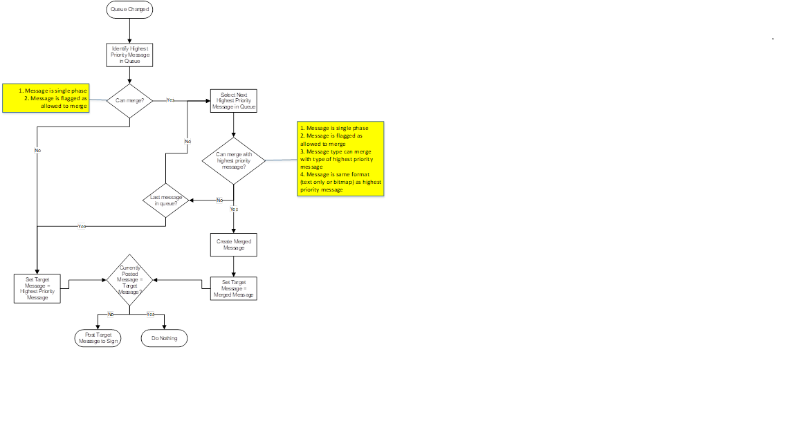
inSIGHT is capable of merging the contents of two messages and posting the resulting message to a sign. In order for two messages to merge, the following must be true:
- Both messages must be single phased
- The two messages must be of message types that are allowed to merge with each other based on system configuration
- Each message must be flagged as eligible to merge, this flag is set based on configuration, but can be changed by users
- Both messages must be text only messages, or both messages must be graphic messages, at this time, graphic messages and text only messages are not combined as they may use different fonts and can present inconsistently formatted messages to the public
When a message is added to or removed from the queue for a sign, the ATMS will use the following workflow to determine what should be posted to the sign.
Graphic Messages
inSIGHT supports graphics in sign messages, where supported by field devices, using background images or left-aligned pictograms. A pictogram library is used to store bitmaps available for use on a sign. Pictograms in the library are stored by display format.
Text in graphic messages is generated by the system using fonts installed on the ATMS server, and not the field controller, to match text messages on signs, the same font should be installed on the server.
When a graphic message is needed on a sign, the sign service constructs full-size graphics and upload the bitmaps to the field. Graphic messages are always sent to sign graphic slots 1 and 2, with the first slot used for the first phase graphic and the second slot used for the second phase graphic.
The only exception to this is the Slotted display type option for Display Formats. In these cases, the system must be configured with a copy of the graphics that appear on the sign controller as well as the graphic slot where that graphic is stored. When activated, the system will only ask the sign controller to display the graphic in the configured slot as opposed to uploading and displaying an image. This functionality is intended for lane control signs, where the graphic slots may be locked to prevent remote overwriting.
Configuration of the pictogram library is not supported through UI configuration tools at this time.
Configuration List
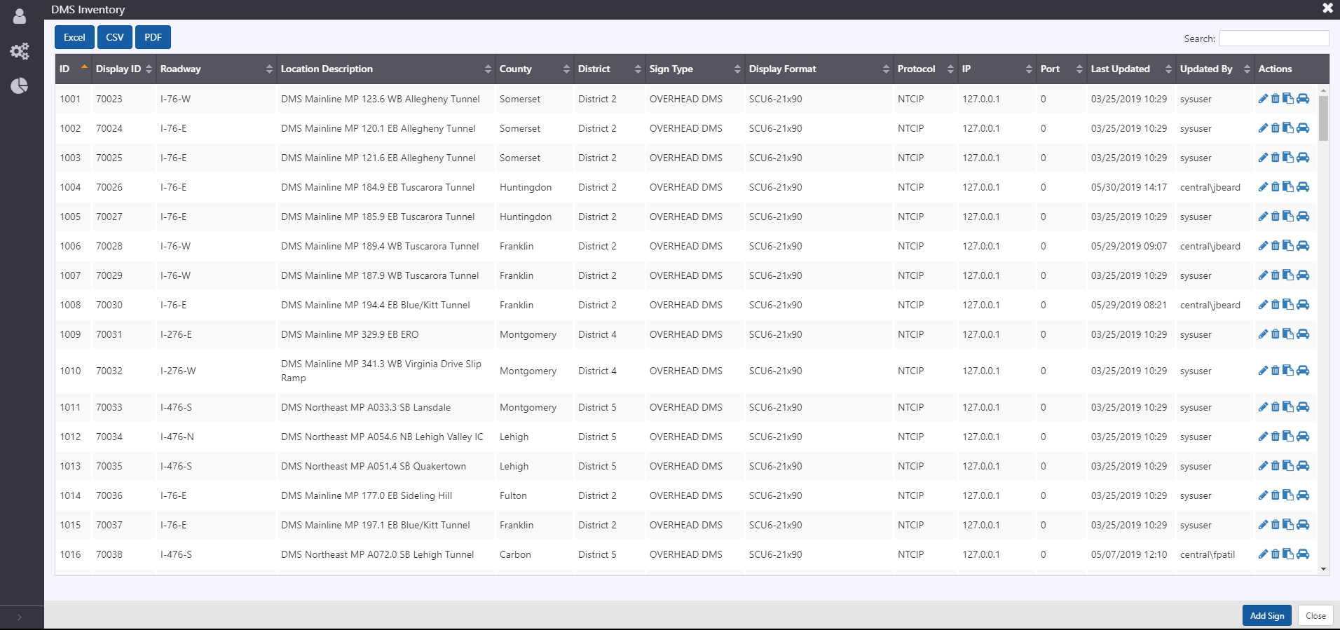
To access a list of all configured Cameras, hover over the configuration icon in the navigation menu and select DMS. A window with list of all DMS configured in the ATMS is populated.
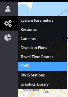
The configuration list window allows user to:
- view a list of configured DMS. See section Sign Configuration for description of information included
- add a new DMS by clicking the
button at the right bottom corner of the window
- delete an existing DMS
- edit configuration of an existing DMS
- copy configuration of an existing DMS and save as a new DMS
- view travel time configuration for the DMS
- export DMS inventory information in Excel, CSV or PDF format
Sign Configuration
Sign configuration is easily accessible from an existing sign, either from the right-click menu on a device, or through the menu at the right of the device in the Sign List. New signs can be added by clicking Add Sign at the bottom of the Sign List.
General Information
All signs require some common information. The general information included for a sign includes:
- ID: unique ID automatically assigned by the system upon creation
- Display ID: integer ID used for internal referencing of the devices
- Contract ID: string ID used for interfacing with external systems
- Description: description of the device
- Public Name: name used to refer to the sign via ATMS API
- Public Description: description used to refer to the sign in ATMS API
- Organization: string to describe what agency is responsible for the device
- Road name: directional roadway associated with the sign, for use in response. Note, signs can also be assigned to the road 'Other' to denote non-agency managed roadways.
- Physical location: latitude and longitude for the physical location of the device
- Display location: latitude and longitude to use as the location for mapping

Communication
Information needed to determine communication to the sign is grouped into Communication, Connection, and Credentials. Communication to signs uses the concept of channels, which represent a series-based communication to device(s) on the channel. IP-based multi-drop devices, i.e. those at the same IP address and port must share a channel. A new channel can be created from the communication screen, or an existing channel can be selected. Clicking select channel will provide a window with a list of configured channels, including other devices currently configured to use that channel.
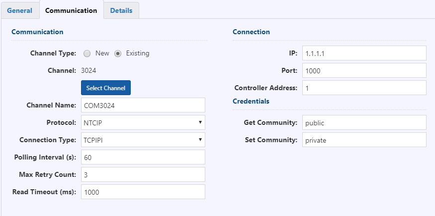
A new channel can be created from the communication screen, or an existing channel can be selected. Clicking Select Channel will provide a window with a list of configured channels, including other devices currently configured to use that channel.
For each channel, the following information is required:
- Channel Name: name to use to refer to the channel
- Protocol: communication protocol to communicate with the sign. Currently supported protocols include NTCIP (v3 and earlier) and Addco SignComm
- Connection Type:
- UDP
- TCPIPI : TCP with NTCIP IPI
- Polling Interval: period of time between successive polls to a sign
- Max Retry Count: number of times to attempt a poll if the initial poll is unsuccessful
- Read Timeout: period of time to wait for a response
Connection information required for a sign includes three items:
- IP: sign controller IP address
- Port: port for sign controller
- Controller Address: HDLC address for multi-drop communication
Two credentials are required for communication, the Get and Set community strings. These strings are only required for NTCIP communication.
Sign Details
Additional information required to configure a sign is included under Sign Details.
The information required here includes the following:
- Display Format: characteristics of the display, such as number of lines, width, and font are associated with a display format. Additional display formats can be configured if needed through Web Config
- Structure Type: type of sign device, such as Overhead DMS or PCMS. Non-PCMS signs are currently entered as Overhead DMS
- Function Type: function of sign display, such as General Purpose, Travel Time, Truck Parking, Variable Speed Limit, Lane Control, Congestion warning or Unspecified
- Track Location: toggle to enable cell modem-based GPS tracking using the PLT service. If enabled, the system tracks the coordinates of these and stores the information in the system to provide operators with latest sign locations. Confirmation on the direction of the roadways is required from operators. This toggle is only available for PCMS
- Use in Response: toggle to enable the sign to be used by Response Manager for event response
- Sign Label
- Default Message: the library messages for the signs display format are available to be selected as a default message. For signs to appear with no message by default, a BLANK library message must be in the message library for that display format
- Travel Time: Click View or Add to edit Travel Time Signing Configuration (See Section : Travel Time Signing ).
PCMS
The PLT service can configure tracking of PCMS. The service will poll a cellular modem for GPS coordinates and display the location in the GUI. When the system determines that the GPS location has exceeded a configurable threshold distance from the previous location, the system will begin tracking the PCMS as moving. The system will poll at a more frequent rate, and once the distance between consecutive polls is below a distance threshold, the system will stop tracking the sign as being moved and generate a notification that the sign's location has changed.
LCS
Lane control sign gantries are configured by associating a sign with a gantry. Signs used in gantries are assumed to be of a display format with the Slotted display type. Configuring a sign as part of a gantry will remove it from the sign list and from the map sign layer. Instead, the device will appear as part of the LCS gantry.
Configuration of LCS gantries and association of signs with gantries is not accessible through the UI at this point. Please contact Arcadis support for assistance configuring LCS gantries.
Graphics Library
Configuration List
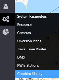
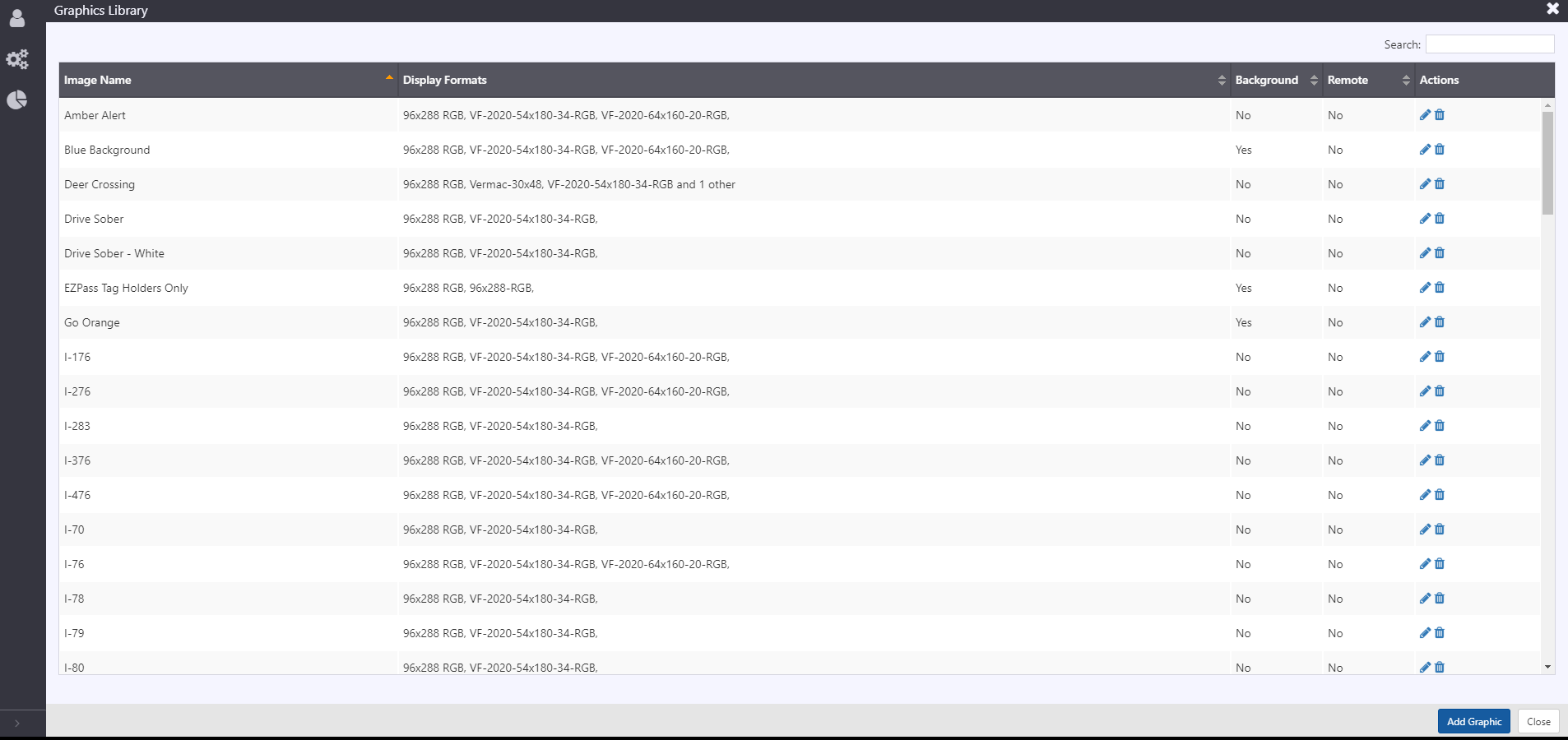
Graphics Library contains list of all configured Graphics that can be loaded on Signs. To access a list of all configured Graphics for Signs, hover over the configuration icon in the navigation menu and select Graphics Library. A window with list of all configured Graphics for Signs in the ATMS is populated.
The configuration list window allows user to:
- view a list of configured Graphics. See section Sign Configuration for description of information included
- add a new Graphics to the library by clicking the
button at the right bottom corner of the window
- delete an existing DMS
- edit configuration of an existing DMS
Graphics Configuration
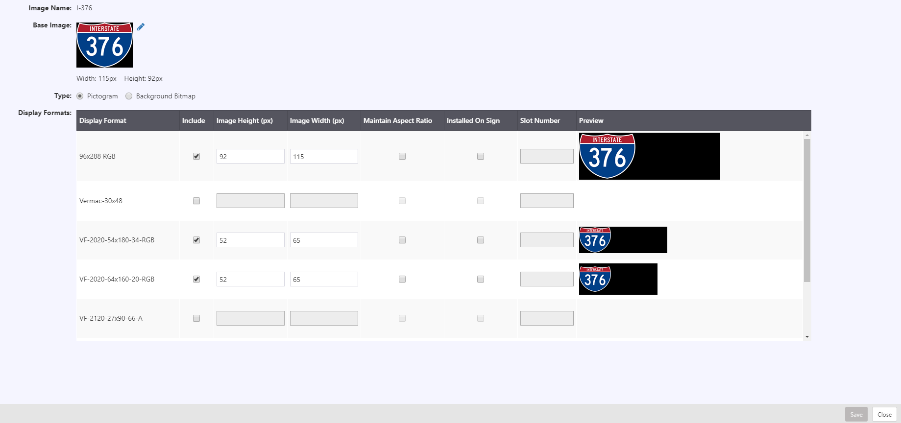
Graphics configuration is easily accessible from the Graphics Library. The Graphic Library Configuration View allows authorized users to manage pictograms or background bitmap images to be used in signs. The information included for each graphic library includes:
Image Details
- Image Name: Descriptive name of image
- Base Image: Base image file associated with this library. Click on
to upload or change image
- Height: (px) shows height of uploaded image in pixels
- Width: (px) shows width of uploaded image in pixels
- Type:
- Pictogram: image included as part of message
- Background Bitmap: image displayed in the sign background
Display Formats
- Display Format: a list of display formats supported by the ATMS is shown.
- Include: checkbox to include display format
- Image Height(px): specify height of the image
- Image Width(px): specify width of the image
- Maintain Aspect Ratio: checkbox, allows system to maintain aspect ratio
- Installed On Sign: checkbox, denoting if the graphic is assumed to be installed in a specific slot on sign controllers of that display format
- Slot Number
- Preview: shows a preview of how image will appear in the sign.
Display Format Configuration
Display Format
Sign display format configuration is available under Web Config. Parameters for a display format include the following:
- Display Format Name: name used to refer to the display format
- Display Type: type of display, based on the following options:
- Line Matrix: line matrix display with a matrix display per line
- Character: fixed number of characters per line
- Slotted: fixed graphics mapped to existing graphics slots on sign controller
- Full Matrix: full matrix display
- Bitmap type: depth of color, either monochrome or 24bit color for color signs.
- Number of Lines: number of lines of text to use in sign messaging
- Number of Characters: number of characters that may appear in one line on a sign for fixed-width fonts.
- Number of Phases: number of allowable sign phases. Three or more phases is not supported at this time.
- Phase Duration: time that each phase should appear on the sign
- Font ID 1: default font for messaging
- Font ID 2: second font for messaging
- Sign Width Pixels: width of the display format in pixels
- Sign Height Pixels: height of the display format in pixels
- Interline Pixels: number of pixels between lines for text messages on full matrix display formats
- Display Attributes: default message characteristics for graphic messages, including font size name, and attributes, and color, text alignment, and offset.
- Default Bitmap Line Spacing: number of pixels between lines for text in graphic messages on full matrix display formats
Font
Font information is stored in tabular form in the system. Font information is used to include the correct information in the multistring for NTCIP-based signs, and for the system to determine if a proposed message will fit on a sign.
Font information includes characteristics about the font:
- Font ID: internal ID to refer to the font
- Font Name: name for reference
- Font Type: fixed or variable width. Fixed font character widths use the same number of pixels, where variable allow for proportional widths.
- Font Code: command string used in communication with sign controllers to indicate what font should be used. For NTCIP signs, the font code is [foX] where X denotes the numeric font slot on the controller where the font is stored.
- Default Character Width: default width in pixels of all characters in this font set. This value is overwritten by entries in DMS Font Character configuration
- Inter Character Width: number of additional pixels between two characters within a word
- Character Height: height of characters in a font set, in pixels.
DMS Font Configuration includes the variable-width exceptions where character widths can be defined to a non-default value for the font set. Entries are not required for fixed-width fonts or font characters in a variable font set that match the default character width. Values in this configuration include
- Font ID: internal ID of the font set
- Character Code: ASCII code of the character
- Width: width of the character in pixels.
Message Queue Configuration
Message Merge
There will be two base levels of configuration for the message merging functionality. The first governs which combinations of message types can be merged together. The second identifies whether the system should automatically merge messages of a certain source.
Combinations of message types that can be merged together can be found in the DMS Message Merge configuration in Web Config. This page allows the entry of two sources which are permitted to merge.
Where it is possible for two messages of the same type to be in the queue at the same time (response messages or scheduled messages), the system will support merging of those messages. For message types like Manual, Travel Time or Default messages where there should be only one message in the queue at a time, the system can be configured to not merge two messages of the same type.
Configuration of message source default merge behavior can be accessed in Web Config under DMS Message Sources. For each message source, a checkbox can toggle if the source defaults to allowing message merge.
Merge Exceptions
It will also possible to configure exceptions that should never be allowed to merge. This will be configured by message name.
For example, Blank messages, which can be set as either Manual or Default priority should never be merged with other messages. There may also be some response messages (such as Wrong Way Driver or full stop/closure messages) that should never be merged, even though some messages within the message hierarchy level these messages belong to might be allowed to merge.
The list of library messages which are not allowed to merge can be modified in Web Config under DMS Message Merge Exception.
Parameters
DMS Manual Message Parameters
| PARAMETER | DESCRIPTION |
|---|---|
| Default Duration | Default message duration for manual messages |
| Grace Period | Extra time added to message duration |
PLT
The PCMS Location Tracking microservice features a number of parameters that are not accessible through the UI. These parameters may be updated on the server at any time with a service restart, however these parameters must be updated by Arcadis in the deployment manager prior to software update or they will be reset. Please contact Arcadis support to update these values.
| PARAMETER | DESCRIPTION |
|---|---|
| Polling Interval | GPS polling period while sign is stationary |
| Polling Interval while Moving | GPS polling period while sign is moving |
| Max Retry Count | Number of times to attempt a poll if the initial poll is unsuccessful |
| Read Timeout | Period of time to wait for a response |
| GPS Poll Port | Port to poll for XORA GPS coordinates |
| Moving Distance Threshold | Distance from previous location for the system to place the PCMS into a move state and start tracking at the move poll frequency |
| Proximity Distance | Distance from previous location for the system to count a moving PCMS as stationary |
| Stop Moving Consecutive Count | Number of consecutive polls in a stationary state for the system to place a PCMS from moving to moved and generate a relocation notification. |